SBM – New lightning protection
INTEGRATION OF A NEW LIGHTNING SURGE PROTECTION BASED ON SILICON CARBIDE CURRENT LIMITER IN AIRCRAFT EQUIPMENT
ABSTRACT
This document describes the surge blocking module, a new lightning component based on SiC material for current limitation. This component is dedicated for high power lightning threats. The purpose of this paper is to study firstly the performances of the surge blocking module as a current limiter against lightning strikes at a mock up level, then integrate it to real aircraft equipment.
Keywords: Lightning Indirect Effect, Surge Blocking Module, Current limiter, Aircraft Equipment
ACRONYMS
A/C : Aircraft
BCI : Bulk Current Injection
CFRP : Carbon Fiber Reinforced Plastic
CS : Conducted Susceptibility
JFET : Junction Field Effect Transistor
LIE : Lightning Indirect Effect
PCB : Printed Circuit Board
PRIM : PRIMary computer
PTC : Pin To Case
SBM : Surge Blocking Module
TVS : Transient Voltage Suppressor
INTRODUCTION
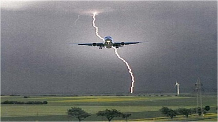
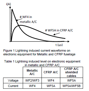
In aeronautics, lightning is one of the most severe threats to avionics components. The current levels generated by the lightning event can range up to several tens of kA and can cause damage to the aircraft structure and potentially disturb the normal operation of electronic equipment. In fact, during a lightning strike, the aircraft structure does not act like a Faraday cage; the electrical energy is coupled to the electronic equipment through the different coupling mechanisms (resistive, capacitive, magnetic effect). This last consequence is referred as Lightning Indirect Effect (LIE), whose constraints are well managed in metallic aircrafts (A/C). However, a more energetic induced waveform must be taken into account for Carbon Fiber Reinforced Plastic (CFRP) fuselage. As could be seen in Figure 1 and Table 1, the CFRP impact on LIE results most of the time in the exposure to a long current wave form WF4 and a much longer and more energetic current waveform WF5A form because of the low conductivity of CFRP material. Thus, the electronic equipment must be designed with specific LIE protection devices to sustain potentially higher energy threats
This paper proposes a new concept of LIE protection integration into aircraft equipment, based on a current limiter to manage higher energies with optimization of equipment weight. The chapter II presents an overview on the existing LIE protection method which introduces the new concept of the Surge Blocking Module (SBM) presented in the chapter III. Finally, the chapter IV describes the measurement results of the integration of the SBM in aircraft equipment.
OVERVIEW ON LIE PROTECTION METHODS
The common protection known as Transient Voltage Suppressor (TVS) is based on Tranzorb technology. If both sides of a circuit are protected with TVS, this solution induces high current into the bundle loops with the additional risk of coupling between wires.
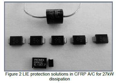
To manage the long waveform in the new CFRP fuselage the TVS method could be applied but the protection device for WF5A will require four times more surface on the printed circuit board than the WF4. At A/C level, the equipment protection is a compromise between installation and equipment robustness. The weight impact is critical. As seen in Figure 2, for a power dissipation of 27kW we either need a through-hole device for LIE protection or five Surface Mount Device (SMD) packages, or a high power Plastic Large Area Device (PLAD), several other solutions exist but do not compromise with the surface saving. For a weight and volume optimization, the new concept proposed as Surge Blocking Module (SBM) consists in increasing the loop impedance. In this case the current stays limited and the dissipated power is low, it can also add a protection against short circuit propagation through the equipment. The last two components shown in Figure 2 are a SBM and TVS; it will be shown later that by combining these two small components, the constraints of the high LIE energies can be managed.
SURGE BLOCKING MODULE (SBM)
Concept of the SBM
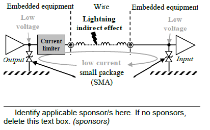
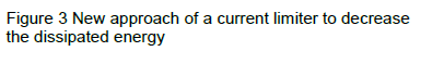
In order to reduce the energy dissipated on the board, the SBM has been developed. Its principle consists in the insertion of a current limiter into the loop composed of a wire and two TVS as seen in Figure 3. In surge stress operation, the TVS device conducts surge current when the surge voltage exceeds the TVS standoff voltage. The in-series SBM limits the surge current to a few 10A, thus allowing use of small, low power, TVS diodes to provide the voltage clamp protection.
A study on surface and volume based on flight computer protection to compare two solutions shows that SBM protection saves 20% of the surface area at the equipment level.
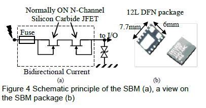
Thus, the current limiter designated as the SBM is a high voltage bidirectional current limiting element implemented using a normally ON N-channel Silicon Carbide JFET technology. The schematic of the new approach is shown in Figure 4. In normal operation, the SBM acts as a low value series resistor (< 1.7Ω for JFETs) and is designed to operate at currents up to ±0.45A.
Lastly, in addition to limiting the current, the SBM integrates a fuse. This fuse element provides “Fail Safe” operation during faults such as inadvertent application of aircraft power. The fuse element is designed to remain intact for the specified lightning surges. However sustained faults, such as the application of aircraft power (115VAC), induce sufficient current to open the fuse and block the propagation of the current. The fuse controlled “limited let-through energy” prevents damage to the Printed Circuit Boards (PCB) and aircraft wiring.
SBM characterization
SBM characterization at mockup level
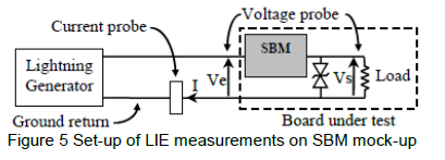
In order to evaluate the performances of the new SBM (ref. DEI1604) combined with a small TVS (ref. SMBJ48CA), several LIE and conducted susceptibility (CS) have been conducted in (1) according to DO160 standard and Airbus directive ABD100. Figure 5 presents the schematic of the test bench for several loads value on a specific designed mock-up.
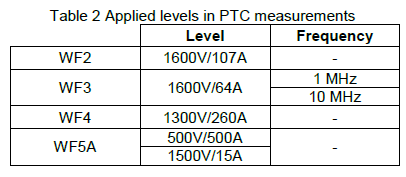
In order to limit the amount of measurements, two values of purely resistive loads have been chosen; 100Ω and 10 kΩ. The following Table 2 summarizes the tested level for the Pin-To-Case (PTC) measurements injected as 10 consecutive pulses and with a negative and positive polarity.
Moreover, conducted susceptibility measurements have been held, according to the DO160E standard (4) to assess the SBM immunity to current injection. The test setup is shown in Figure 6. As described in the DO160 standard, the Bulk Current Injection (BCI) measurements are performed between 100 KHz – 400 MHz for CW and AM (90%). The injected current is set to 75 mA with a current limitation up to 250 mA. The test bench is composed of a SBM, a TVS (SMBJ43CA) and the protected interface.

The next paragraph will show the experimental results of PTC and BCI measurements at mockup level before the presentation of the SBM integration into A/C equipment.
SBM characterization results
Pin-To-Case measurements results
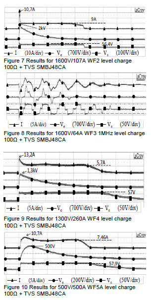
The lightning damage results shown in Figure 7 to Figure 10 show that the SBM has fulfilled its function of current limiter and the TVS limited the voltage across the load. In the different figure Ve is the injected voltage, Vs is the output voltage and I is the limited current in the loop as shown in Figure 5.
The results of the different waveforms have demonstrated that the SBM limits the maximum current to less than 13 A and the TVS limits the voltage to less than 57 V which reduce intensively the energy in the loop. The measurements with a 10 kΩ load have led to the same conclusion.
Conducted susceptibility results
In order to assess the immunity performances of the SBM prior to its integration in A/C equipment, the response of the current limiter device is evaluated through BCI measurement following the test setup presented in III-B-1. The same measurement is performed on a TVS as it is a common solution for LIE protection and will be considered as reference level.
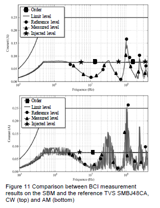
The following Figure 11 shows the BCI measurements results in CW (top) and AM (bottom). The measurement level on the SBM is very similar to the reference level obtained in the TVS. These results demonstrate that the SBM should not modify the susceptibility level of equipment. However, since the measurements on a fixed load are not representative of real A/C equipment, susceptibility measurement will be performed after the integration of the SBM in A/C equipment. The results are not shown in this paper; a special focus will be given to LIE measurement.
SBM INTEGRATION IN A/C EQUIPMENT
Presentation of the test setup
The verification of the SBM technology on a real flight control computer was carried out. The lightning protection system was replaced by the SBM for some interfaces and compared to the TVS protection system. In order to assess the conformity of the SBM integration, this section presents the first experimental setup and results for lightning induced transient susceptibility as described in section 22 of the DO160E standard (3). Figure 12 presents the test setup of cable bundle injection. It is composed of A/C equipment (Primary Computer (PRIM)) monitored by a test bench and the assembly of lightning generator and a tore for injection on each bundle. The equipment power supply is connected to a Line Impedance Serial Network (LISN) and all the ground connections are strapped to the copper ground plane. The tests are performed for the WF3 up to 1500V/60A (1MHz and 10MHz) and for WF5A the level 500V/500A and up to 2000V/20A.
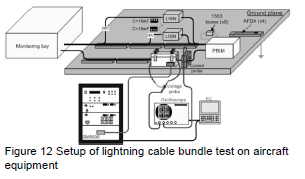
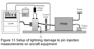
Figure 13 presents the test setup for the damage to pin injection test. It is composed of A/C equipment (Primary Computer (PRIM)), the injection clamp connected to the lightning generator and the measurement current probe. During this test only the WF5A (500V/500A) has been tested since it is the most energetic wave form as described in the introduction. Although, the SBM is more vulnerable to voltage than current because it by definition it avoids circulation of the current, this WF5A level has been chosen to assess the limitation performances of the SBM. All the tests have been performed on A/C equipment with TVS protections and a second one with SBM protection.
Presentation of LIE measurement results
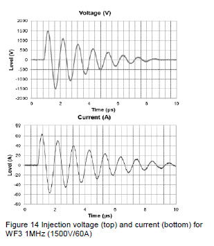
Figure 14 shows the injected voltage and current in cable bundle test for WF3 1MHz 1500V/60A. Since the equipment was monitored, no error has been recorded and no susceptibility is signaled. The same test was performed for the other injection levels and wave forms and no susceptibility appears.
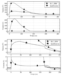
The comparison results of the pin to case tests are presented in Figure 15. It shows that for a 500V/500A injection on a single pin, the SBM is limiting the current to less than 12 A.
CONCLUSION
A new device based on the surge blocking technology has been presented. The main objective of the integration of this component is enhancing the performance of LIE protection on printed circuit boards by limiting the energy. As a design optimization this solution can be used without taking into account A/C zoning. Moreover, the weight and surface saving at the equipment level with this kind of protection can be close to 20%. As could be seen in this paper, it was demonstrated that the SBM associated with a small TVS can protect I/Os against very high current strikes. LIE measurements have shown that the current stays below 12 A, and BCI measurements are conclusive since the integration of this device should not add any susceptibility into A/C equipment. As a perspective of this work, we work on the improvement of the SBM performance by increasing the current rating and reducing Ron in order to protect the power lines. Moreover, the current SBM can operate up to ±0.45A on normal operating conditions, thus, it can be improved to handle higher operating current and sustain higher LIE level (5).
REFERENCES
- A. Sauvage, L. Bui, N. Monnereau, W. Cheung, T. Tammen, « New concept using silicon carbide current limiter device for Lightning surge protectiion of embedded Aircraft Equipments » EMC Europe, 2013
- ABD0100.1.2 issue G; Airbus Directives; “Environmental Conditions and Tests Requirements Associated toQualification”; Chapter 3.2 “ Lightning”; 2008
- DO-160E/EUROCAE ED-14E; “Environmental Conditions and Test Procedures for Airborne Equipment” Section 22 “Lightning Induced Transients”; 2005
- DO-160E/EUROCAE ED-14E; “Environmental Conditions and Test Procedures for Airborne Equipment” Section 20 “Radio Frequency Susceptibility (Radiated & Conducted)”; 2005
- P. Ku, T. Tammen, C. Ghfiri, A. Sauvage; “Enhacing the lightning surge protection level and operating current capacity of the SiC Surge Blocking Module” ICOLSE, 2019